READINESS / OWNERSHIP
Edge E3 architecture atlas
RV32 + independent ASIC enginesCHAPTER 01
System architecture
A four-stage RV32 pipeline. Captured GPR parameters. Start to fork; sync to join.
1.1 Pipeline & command paths
CHAPTER 02
Tensor
Descriptors, local weights, accumulation and scale delivery.
2.1 Datapath & operating modes
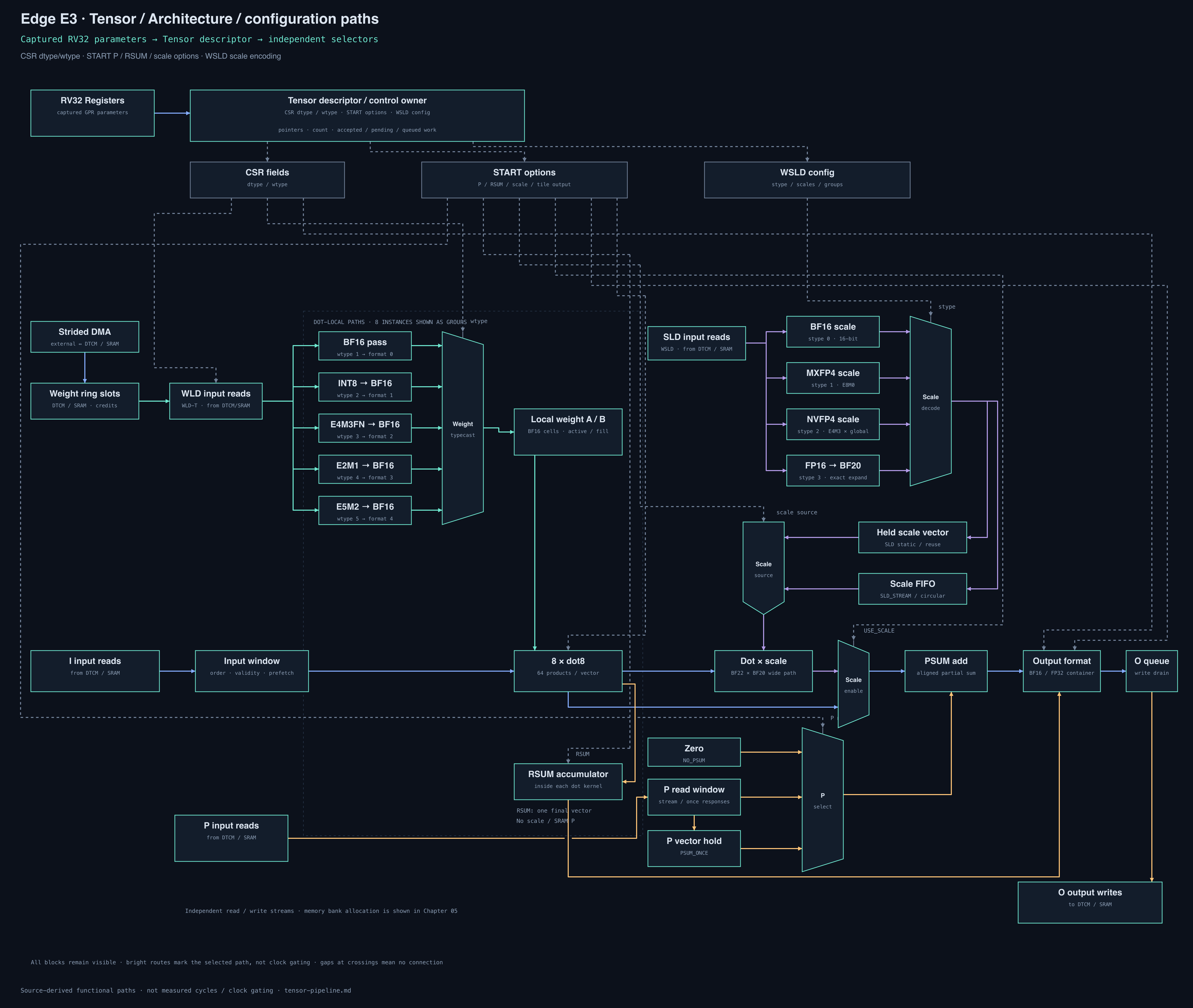
The reference slide decks explain feeding, buffering and mapping GEMM loops onto Tensor jobs. The paths below follow the maintained src implementation. A job is a weight tile plus a stream of vectors, with owned input, partial-sum and output state.
ONE CONCRETE GEMMW[16 × 24] × X[24 × 8] = Y[16 × 8]
Split W into six 8 × 8 tiles. Each start reuses one weight tile for P = 8 input vectors. Three Q blocks contribute to each output block.
WORK PER START8 vectors × 8 dot8 results
Eight dot kernels each reduce eight products: 64 products per admitted vector. Software schedules tile jobs; hardware streams their vectors.
SELECT A CONFIGURATION PATH
Inspect one control family at a time. These buttons show selected paths, not a combined software configuration. Weight codes are cast at dot-local ingress; scale codes are decoded by the WSLD slot reader.
Open full-resolution PNG ↗Fit the full path, or expand and scroll to read each port.
Blue: input / outputTeal: weightsAmber: partial sums / writebackPurple: scale dataGray dashed: descriptor controlAll blocks stay visible; bright routes show the selection
2.2 Scheduling & accumulation
Three overlapping responsibilities
ScalarDescribe NDescribe N+1Describe N+2DMA / WLDFeed NFeed N+1Feed N+2TensorRun N / ARun N+1 / BRun N+2 / A
Logical scheduling slots, not clocks. DMA/WLD is one feeding responsibility in this illustration, not one physical RTL stage. Overlap requires ready descriptors, weights, operands and output capacity. Continuous compute is conditional; this view makes no utilization claim.
Current matmul accumulation modes
| Tile mode | P input | O destination |
|---|---|---|
| FIRST_TILE | Zero / NO_PSUM | 32-bit partial-sum storage |
| PSUM_TILE | Previous partial sum | 32-bit partial-sum storage |
| LAST_TILE | Previous partial sum | BF16 output |
| SINGLE_TILE | Zero / NO_PSUM | BF16 output |
The maintained tiled BF16 runtime distinguishes first, intermediate and final reduction tiles. This extends the older slide’s simplified NO_PSUM/default sequence. Read matmul.hpp and the start-mode definitions for the actual calls and packed layout. The standalone 64 × 64 example below instead uses explicit zero/psum pointers.
Slide references and implementation boundaries
The local source decks are ~/slides/Chapter2/slides.mjs and ~/slides/Chapter3/slides.mjs; page numbers follow their combined-deck manifest. Their examples guide the explanation; source RTL defines the current behavior.
- The slide’s eight-channel butterfly is a conceptual memory explanation. The product-default wide-H4 engine uses sixteen 64-bit banks, four-edge SRAM read latency, response windows and bank-conflict handling. Logical I/P/O/WLD/DMA streams are not dedicated physical ports.
- The arithmetic backend instantiates eight parallel dot kernels with local weight cells. No literal systolic topology is asserted.
- The older command-queue illustration is not asserted as a module on the maintained Edge32 dispatch path. Current Tensor ownership includes pending/queued starts and capacity backpressure.
- The slide’s old
cpp/libnn/matmul.hpppath now corresponds tosrc/edge-nnc/cpp/libnn/matmul.hpp; the current runtime uses explicit tiled accumulation modes. - The mechanism diagram is source-derived. The measured trace below offers separate ACTU and Tensor matmul captures; use its workload selector to inspect actual Tensor overlap.
2.3 Software walkthrough
A tiled job, from pointers to joinsExpand / collapse
Selected lines from the maintained 64 × 64 × 128-token example. Memory initialization, DMA setup and loop bodies are omitted from the excerpt. Steps explain ordering; they are not measured clock cycles.
C++ / SOURCE EXCERPTFull example ↗
CHAPTER 03
ACTU
Shared nonlinear arithmetic, from numerator and divisor to BF16 output.
3.1 Datapath & operating modes
Sigmoid, SiLU and tanh share the expensive exponential route. The front half prepares the numerator and divisor; the back half applies reciprocal or reciprocal square root, then combines aligned operands. Softmax uses two software-controlled passes.
Open this mode as PNG ↗Bright: selected result path · Muted: result unused
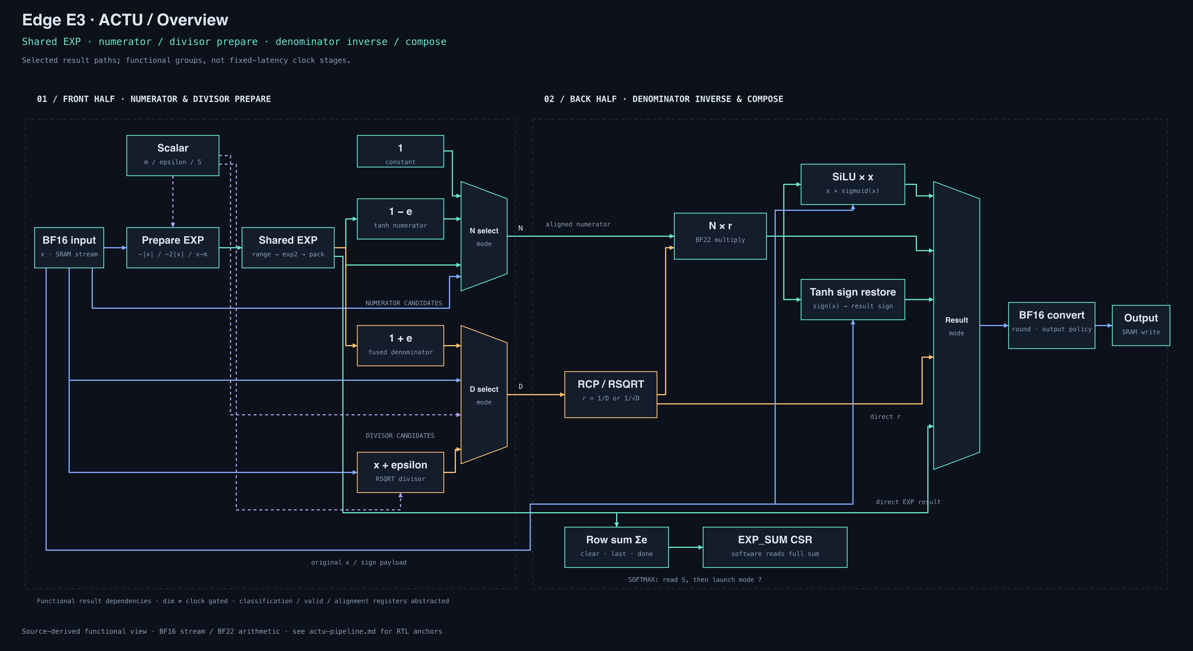
Blue / input and payloadGreen / EXP and numeratorAmber / divisor and inversePurple dashed / scalar parameter
Mapping the slide identities onto the RTL
| Function | Shared exponential | Numerator | Denominator | Final composition |
|---|---|---|---|---|
| Sigmoid | e = exp(−|x|) | x < 0 ? e : 1 | 1 + e | N × reciprocal(D) |
| SiLU | e = exp(−|x|) | x < 0 ? e : 1 | 1 + e | x × N × reciprocal(D) |
| Tanh | e = exp(−2|x|) | 1 − e | 1 + e | restore sign of N × reciprocal(D) |
| Softmax · pass 1 | eᵢ = exp(xᵢ − m) | eᵢ | reduce S = Σeᵢ | store eᵢ and publish S |
| Softmax · pass 2 | unused | stored BF16 eᵢ | scalar S | eᵢ × reciprocal(S) |
The mathematical forms in the reference slide explain reuse. This diagram follows the stable magnitude-based RTL, with sign restoration and a separate Softmax normalization pass. BF16 is the SRAM stream format; the arithmetic uses BF22 and a carried BF19 payload. The drawing groups registered transport, semantic classification and special-value handling to keep the numerical paths readable. Source map and boundaries ↗
3.2 Software walkthrough
Sigmoid beside scalar instructionsExpand / collapse
Maintained self-checking example: 4,096 BF16 zeros → sigmoid → 0.5. The excerpt below precedes the shared execution story and the measured ACTU trace.
C++ / SOURCE EXCERPTFull example ↗
Mode 2 selects the shared sigmoid path.
Configure BF16 mode 2, input, output and count. edge_actu_start() submits work; the scalar loop then executes 32 increments. edge_actu_sync() waits for the target drain, after which the example checks every output.
The diagram above explains arithmetic. The timeline below explains ownership; the measured trace shows actual cycle observations.
Inspect measured trace ↓CHAPTER 04
Execution & synchronization
Follow ownership from fork to overlap, backpressure and join.
4.1 Fork, overlap & join
Illustrative ordering · not an RTL cycle trace
Engines can overlap, subject to dependencies, ready/backpressure and shared-memory arbitration. Sync waits only for earlier work on its selected target.
4.2 Measured RTL traces
Self-checking public examples
See scalar progress while ACTU runs.
Full Tensor capture PNG ↗ · Detailed overlap / A-B / drain windows ↗. Software command acceptance, internal compute launch and Compute input valid are distinct events.
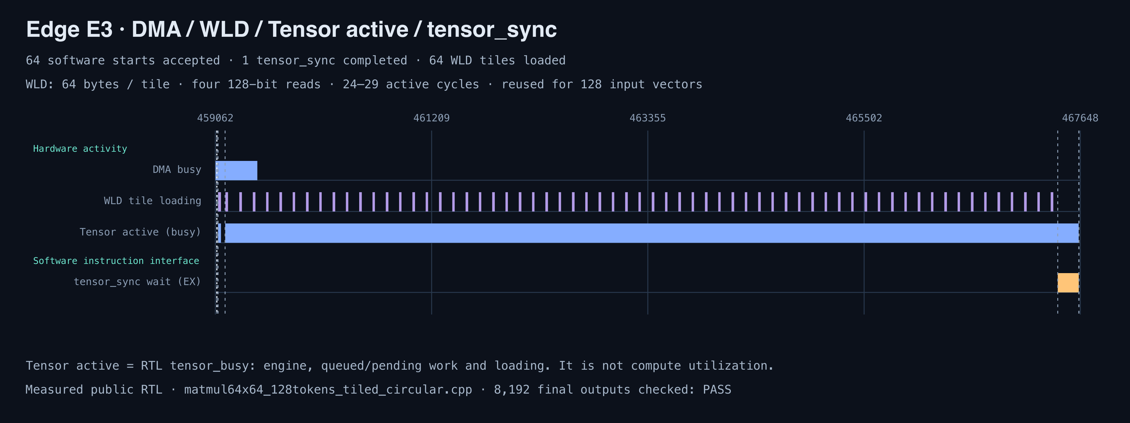
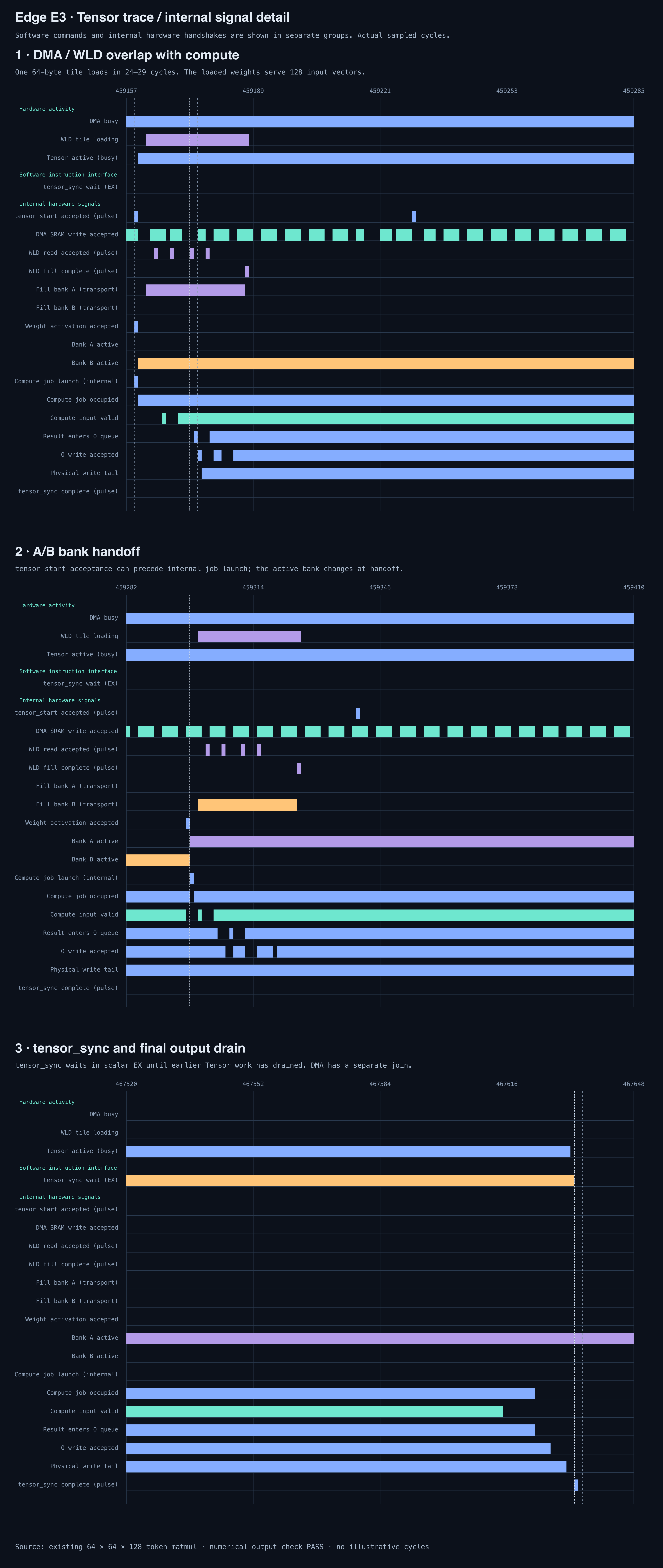
High bars mean the signal is true at that edge. A/B identify physical bank 0/1, qualified by weight validity; activation takes effect at the edge. Accepted reads/writes are distinct from physical write-tail visibility. Click an event to select its architecture path above.
Captured commands and run provenance
Transport payloads are shown verbatim. Operand-free start/sync commands do not consume a GPR parameter.
Reproduce: ./example/fork_join/run.sh · Build, checks and trace definitions ↗. Raw CSV, ELF and run report remain in the example’s ignored build directory.
4.3 Backpressure & admission
What waits, and what keeps running?
4.4 Key concepts
Parameters travel with instructions
IF supplies GPR read indices. ID operand-use controls select the read values captured into EX. Later scalar writes cannot change parameters in an accepted command.
Start launches hardware work
The target progresses independently after launch. Scalar continues after the command response. Acceptance, launch and whole-job completion are distinct events.
Sync waits in EX
A pending sync retains EX ownership and backpressures admission. Engines keep running, and older WB work may still retire. The response releases scalar execution.
CHAPTER 05
SRAM scheduling
Butterfly routing, wide/narrow bank allocation and buffered clients.
5.1 Rotation & service explorer
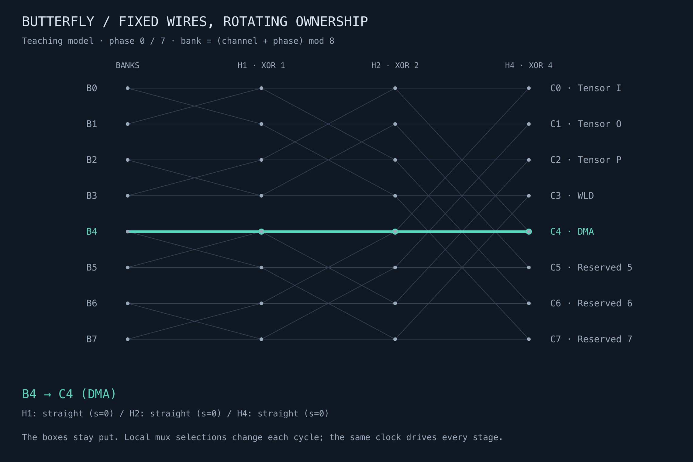
The Chapter 2 butterfly is a teaching model: eight fixed channels visit eight bank positions over eight phases. Follow a selected route through H1, H2 and H4, then inspect the current DTCM bank-door rotation and buffered consumers. Fast / slow service follows the same phase buttons and lets P and O independently select FP32 or BF16.
PHASE
5.2 Routing rules & implementation scope
What changes each cycle?
Each butterfly stage chooses straight or exchange routing. H1, H2 and H4 exchange rows at distances 1, 2 and 4. Their local selectors have different initial offsets; a single global square wave per stage is insufficient. These are mux controls in one clock domain, not divided clocks.
The highlighted path runs from bank to consumer. Writes use the corresponding inverse permutation. A channel visits every bank exactly once per eight-phase teaching tour.
What the simplified slide leaves out
Current DTCM has 16 × 64-bit banks. Fast O/P storage streams use 256-bit beats; slow I/O/P BF16 streams use 128-bit beats. These service classes coexist in the wide schedule. Indexed reorder state restores logical beat order after physical rotation.
LSU, ACTU and CMPU consume the slow service through adapters and buffering. ACTU/CMPU own explicit read queues and write FIFOs; the LSU boundary forwards ready/response. Shared admission, credits, row carries and dependencies still matter. Fixed rotation does not guarantee bubble-free execution.
Sources, scope and reproducibility
Teaching reference: ~/slides/Chapter2/slides.mjs and evidence/rotation-mapping.json. The 64 bank-to-channel paths are checked independently by verify.mjs. The eight-channel diagram is not the current physical netlist or a measured trace. Current service widths and queue ownership follow the maintained sources below.